
designed to separate a gas-liquid mixture into fractions with different characteristics
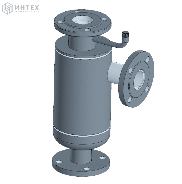

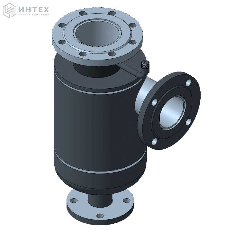

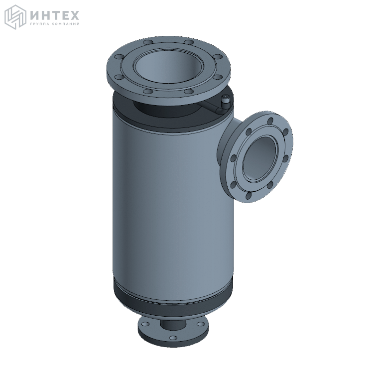
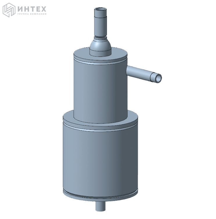
Application Area
The VGS X-06.X gas separators are designed for deep cleaning of air and gas streams from droplet, fine-dispersed, aerosol moisture, oil, and foreign impurities, as well as for the accumulation and periodic discharge of water-oil condensate.
The gas separator is used in pneumatic systems primarily for final cleaning and drying of compressed air. It is installed directly before pneumatic actuators, cleaning the compressed air coming from the main line.
The gas separator is also used in gas preparation systems, gas-air mixtures, and compressed air systems for preliminary cleaning of compressed air before supplying it to the main line. It is installed after the compressed air cooler, if present, and before the adsorption dryer, if present.
The gas separator can be used in supply and return steam pipelines (using steam as a heat carrier) to stabilize pressure and remove condensate from the system.
Download the Inquiry Form for the Vortex Gas Separator VGS
Design and Operating Principle of the Gas Separator
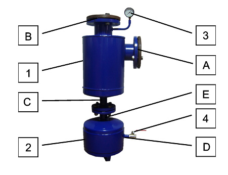
Structurally, the gas separator consists of two pressure vessels. (Fig.1)
– the upper vessel – the separation tank (1);
– the lower vessel – the condensate collector (2).
The separation tank (1) has an inlet nozzle (A) for supplying compressed air, an outlet nozzle (B) for discharging cleaned compressed air, and a nozzle (C) for draining condensate into the condensate collector (2). The separation vessel is equipped with a pipe for mounting a pressure gauge (3) or a three-way valve used for sampling and monitoring the quality of compressed air.
The condensate collector (2) has an inlet nozzle (E) for receiving condensate and a pipe (D) with a drain valve (4) for discharging condensate.
The gas-liquid mixture is supplied to the apparatus through the inlet nozzle (A) located in the upper part of the separation tank and enters the inlet device, which provides tangential supply of the incoming flow into the gas separator body.
In the space formed by the body wall and the separation pack, the main mass of liquid is separated from the gas stream due to centrifugal forces. This liquid is transported by gravitational forces along the gas flow in a descending spiral to the drain nozzle (C) located at the base of the body.
The gas stream containing fine-dispersed droplet liquid, which has not settled on the body, enters the convex surface of the separation pack plates, where the gas-liquid mixture is stratified.
The liquid settled on the plate surfaces is transported downward and away from the center under the action of centrifugal force and gravity, while the cleaned gas stream enters the central area through the nozzle channels and is directed to the outlet nozzle (B).
The liquid with solid impurities enters the condensate collector (2) through the drain nozzle (C), from where it is discharged as the collector fills.
Classification and Selection of the Gas Separator
VGS units are distinguished by the volumetric flow rate of air measured in normal (non-compressed) cubic meters per minute (nm³/min) and the compression pressure in MPa.
Consider the example of the gas separator designation – VGS1-06.3, where:
VGS – abbreviation of the name – Vortex Gas Dynamic Separator;
1 – the digit indicates the working pressure of the VGS and is selected according to the table:
| Separator Model | VGS 1-06.X | VGS 2-06.X | VGS 3-06.X | VGS 4-06.X | VGS 5-06.X | VGS 6-06.X |
| Working Pressure, MPa | 1.0; 1.6 | 2.5 | 4 | 6.3 | 10 | 16 |
3 – the digit indicates the volumetric flow rate of air measured in normal (non-compressed) cubic meters per minute (nm³/min) and is selected according to the table:
| Gas Separator Model | VGS X-06.5 | VGS X-06.1 | VGS X-06.2 | VGS X-06.3 | VGS X-06.4 |
|
Flow Rate, nm³/min
|
2.5 | 10 | 25 | 50 | 100 |
The gas separator is selected after measuring the flow rates on the compressed air line over several work shifts. The minimum and maximum compressed air flow rates on the line should be identified, and the average compressed air flow rate should be calculated.
If at least one parameter of your working medium (air, gas, etc.) does not match, we develop a new VGS model in accordance with the specific characteristics of your working medium (pressure, flow rate).
At the customer's request, any changes can be made, which are agreed upon before ordering. Below are some of them:- type of mounting (standing, suspended, etc.);
- type of flanges (flat according to GOST 12820, collar according to GOST 12820, etc.);
- flange design by gasket type (flat, tongue-and-groove, oval section, etc.);
- disassembled and non-disassembled;
- design with a built-in condensate collector.
Gas Separator Configuration
The delivery package is usually agreed upon in advance. Below is a list of the most frequently included items:
- condensate collector;
- mating flanges with fasteners and gaskets;
- spare parts: fasteners and gaskets;
- self-regulating heating tape;
- indicating pressure gauge;
- three-way valve;
- automatic drain;
- manual condensate drain valve.
Installation Diagram
The connection of the VGS gas separator nozzles is carried out in accordance with the diagram:
For ease of understanding the VGS connection, an example of its installation on an existing pipeline is provided. This example is also applicable for newly designed pipelines.

At the point in the pipeline where the VGS gas separator is planned to be installed, a certain section is cut out, the length L of which depends on the separator model. If the diameter of the working medium inlet nozzle differs from the pipeline diameter, the length of the cut section will be L1.
Next, the gas separator is connected to the supply pipeline with the medium inlet nozzle and connected to the other end of the pipeline using a system of nozzles and bends.
Since the medium inlet and outlet nozzles are offset from the main axis of the VGS separator, with each having its own offset value, the nozzle system will look as shown in the diagram:

Advantages of VGS Gas Separators
Trial operation – we provide the opportunity to test the separators.
Flexibility – We create new gas separator models specifically for you in accordance with the specific characteristics of your working medium (air, gas, etc.) completely free of charge.
High efficiency – always a quality product at the output.
